
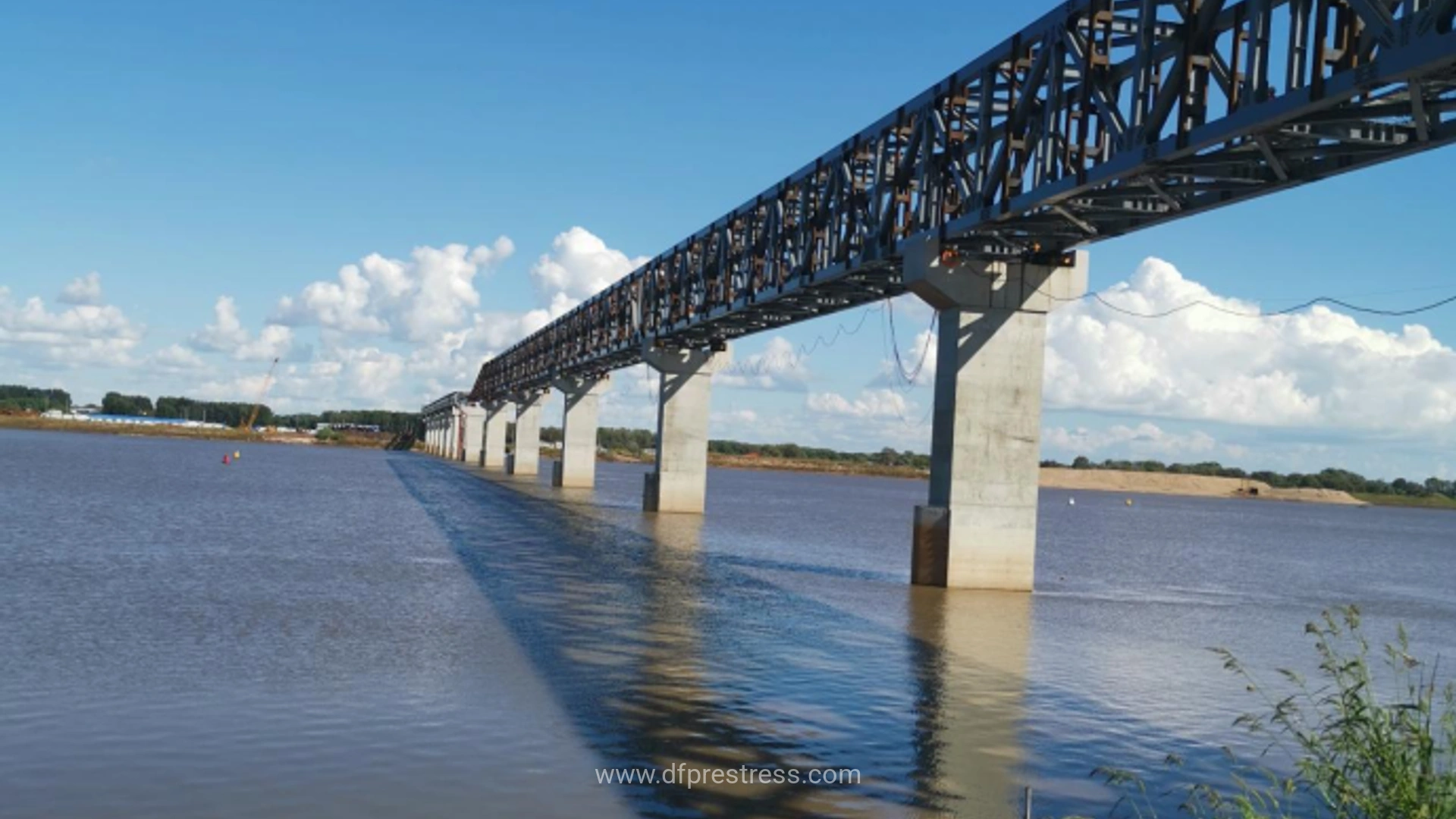
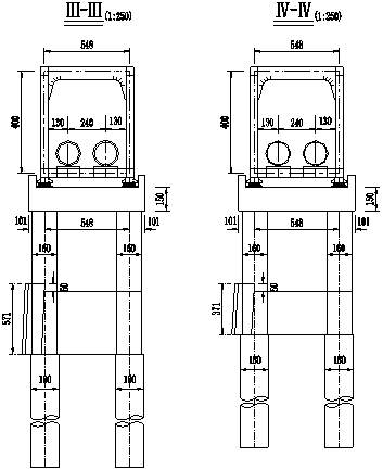
The main bridge has two links, both of which are 3X65m bearing continuous steel truss bridge. The length of main truss is 6.5m. The main truss height is 6.5m, and the height span ratio is 1 / 10. The distance between the main centers of the two main trusses is 5.48m, and the width span ratio is 1 / 11.86. The clearance width is 5.0m. The upper and lower strings of the main truss adopt box section, and the internal width is 440mm, and the section height is 550mm.

The approach bridge has 3 links, which is the 40m simple supported steel truss beam of fulji side- ~ hole and Qiqihar side- -joint 4X40m and- -joint continuous steel truss beam of 3X40m. All are lower bearing steel truss Bridges. The length of the master cypress is 4.0m. The main truss height is 4.0m, and the height span ratio is 1 / 10. The distance between the main cores of the two main trusses is 5.48m, the width span ratio is 1 / 7.299, and the bridge deck guarantees the pipeline operation clearance of 5.0m. The upper and lower strings of the main truss adopt a work-shaped section to control the full width and height.

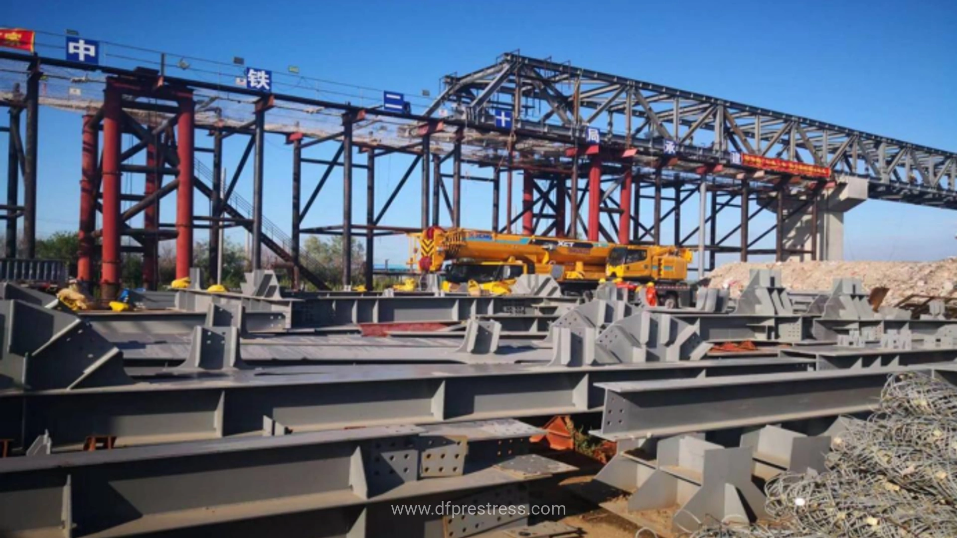
According to the structural situation of the bridge and combined with the field investigation, the steel truss girder of 2 (365) m on the main bridge is planned to set temporary steel pipe support between 0 # and 2 # pier as temporary support and jacking platform, and a 50t crawler crane is laid in this area, and then assemble the steel truss girder with crawler crane; the jacking slide is set between 0 # -2 # pier and 2 #, 2 #, 3 #, 4 #, 5 # and 6 #; the overall elevation layout is shown in the following figure;
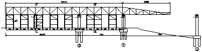
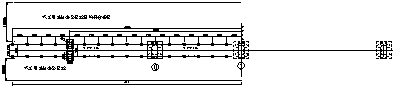
Top pushing elevation and plane layout of steel truss beam of main bridge
Set the 340m + 440m steel truss girder on the shore after the 14 # pier as the temporary support and the jacking platform, lay a 80t crawler crane in this area, and then assemble the steel truss girder on 1 # -2 # and temporary pier # 8 #, 9 #, 10 #, 11 #, 12 #, 12 #, 13 # and 14 #. See the overall elevation layout in the following figure;
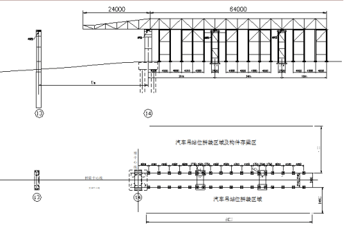
Top push elevation and plane layout of steel truss beam of approach bridge