
01
Material Preparation
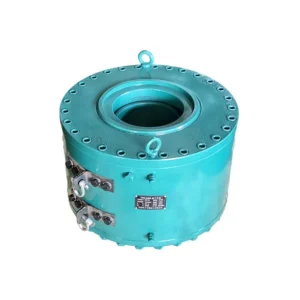
Raw Material Cutting
Selected steel materials are cut into the required dimensions for subsequent precision machining and component manufacturing.
Please provide details on the strand layout, required tension, travel, and anchorage.
Share the load at each point, number of points, movement, closed height and available space.
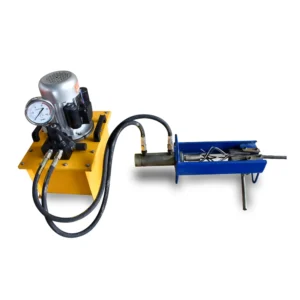
Please provide its pressure, flow rate, control method, and connection type, as well as the on-site power supply conditions.
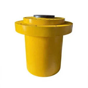
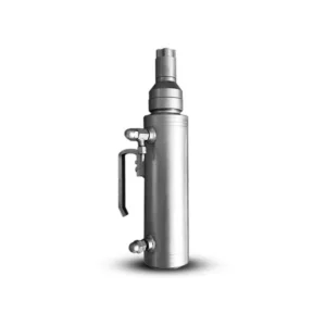
Prestressing Anchors, Center-Hole Hydraulic Jacks, Specification Comparison Table
| Specification | Anchor Head | Bearing Plate | Duct | Spiral Reinforcement | Duct | Spiral Reinforcement | ||||||
|---|---|---|---|---|---|---|---|---|---|---|---|---|
| ΦD | B | A | L | ΦF | a | ΦC (ID) | ΦG | t | Φd | n | Stressing Jack | |
| YM13-1 | 40 | 50 | 90 | 35 | – | 70 | 85 | 35 | 6 | 4 | QYC270 | |
| YM13-2 | 80 | 50 | 120 | 110 | – | 80 | 40 | 110 | 50 | 8 | 3 | YDC650 |
| YM13-3 | 80 | 50 | 120 | 110 | – | 80 | 50 | 130 | 50 | 8 | 3 | YDC650 |
| YM13-4 | 85 | 50 | 135 | 120 | – | 95 | 50 | 160 | 50 | 10 | 4 | YDC650 |
| YM13-5 | 94 | 55 | 150 | 120 | – | 110 | 50 | 160 | 50 | 14 | 4 | YDC1500 |
| YM13-6,7 | 108 | 55 | 165 | 150 | 140 | 125 | 60 | 190 | 50 | 14 | 5 | YDC1500 |
| YM13-9 | 128 | 60 | 180 | 160 | 130 | 140 | 60 | 220 | 50 | 16 | 5 | YDC1500 |
| YM13-12 | 148 | 60 | 215 | 190 | 150 | 175 | 80 | 240 | 60 | 16 | 5 | YDC2000 |
| YM13-19 | 178 | 65 | 270 | 250 | 180 | 230 | 90 | 310 | 60 | 18 | 6 | YDC3000 |
| YM13-22 | 188 | 65 | 290 | 260 | 200 | 250 | 100 | 330 | 60 | 18 | 6 | YDC3000 |
| YM13-24 | 208 | 75 | 300 | 270 | 230 | 260 | 100 | 340 | 60 | 18 | 6 | YDC5000 |
| YM13-25,27 | 208 | 80 | 320 | 280 | 245 | 280 | 100 | 360 | 60 | 18 | 6 | YDC5000 |
| Specification | Anchor Head | Bearing Plate | Duct | Spiral Reinforcement | Duct | Spiral Reinforcement | ||||||
|---|---|---|---|---|---|---|---|---|---|---|---|---|
| ΦD | B | A | L | ΦF | a | ΦC(ID) | ΦG | t | Φd | n | Stressing Jack | |
| YM15-1 | 48 | 50 | 90 | 35 | 70 | 80 | 30 | 6 | 4 | QYC270 | ||
| YM15-2 | 93 | 50 | 135 | 110 | 85 | 45 | 120 | 40 | 8 | 4 | YDC650 | |
| YM15-3 | 93 | 50 | 135 | 110 | 85 | 50 | 130 | 40 | 10 | 4 | YDC650 | |
| YM15-4 | 98 | 50 | 150 | 120 | 100 | 55 | 150 | 50 | 10 | 4 | YDC1500 | |
| YM15-5 | 108 | 50 | 180 | 130 | 130 | 55 | 170 | 50 | 12 | 4 | YDC1500 | |
| YM15-6,7 | 128 | 55 | 190 | 160 | 140 | 140 | 70 | 190 | 50 | 12 | 4 | YDC1500 |
| YM15-8 | 138 | 55 | 230 | 180 | 160 | 180 | 80 | 230 | 60 | 14 | 5 | YDC2000 |
| YM15-9 | 154 | 58 | 240 | 190 | 170 | 190 | 80 | 240 | 60 | 14 | 5 | YDC2000 |
| YM15-10 | 158 | 60 | 250 | 210 | 180 | 200 | 80 | 250 | 60 | 16 | 6 | YDC2500 |
| YM15-11,12 | 168 | 60 | 260 | 210 | 180 | 210 | 90 | 260 | 60 | 16 | 6 | YDC2500 |
| YM15-13 | 176 | 65 | 260 | 210 | 190 | 210 | 90 | 260 | 60 | 16 | 6 | YDC3000 |
| YM15-14 | 187 | 65 | 270 | 220 | 190 | 220 | 90 | 270 | 60 | 16 | 6 | YDC3000 |
| YM15-15 | 187 | 65 | 290 | 230 | 210 | 240 | 90 | 290 | 60 | 16 | 6 | YDC4000 |
| YM15-16 | 207 | 65 | 290 | 250 | 210 | 240 | 90 | 290 | 60 | 16 | 6 | YDC4000 |
| YM15-17 | 207 | 70 | 310 | 265 | 220 | 260 | 100 | 310 | 60 | 18 | 7 | YDC4000 |
| YM15-18,19 | 207 | 70 | 310 | 265 | 220 | 260 | 100 | 310 | 60 | 18 | 7 | YDC4000 |
| YM15-22 | 227 | 70 | 330 | 265 | 230 | 280 | 120 | 330 | 60 | 20 | 7 | YDC4600 |
| YM15-24 | 237 | 75 | 330 | 280 | 240 | 280 | 120 | 330 | 60 | 20 | 7 | YDC6500 |
| YM15-25,27 | 247 | 90 | 380 | 300 | 250 | 330 | 120 | 380 | 60 | 20 | 7 | YDC6500 |
| YM15-31 | 277 | 90 | 390 | 355 | 300 | 340 | 130 | 390 | 70 | 22 | 8 | YDC6500 |
| YM15-37 | 287 | 100 | 430 | 435 | 320 | 380 | 140 | 430 | 70 | 22 | 8 | YDC8000 |
| YM15-44 | 327 | 110 | 460 | 465 | 350 | 410 | 160 | 460 | 70 | 22 | 8 | YDC10000 |
| YM15-55 | 360 | 120 | 530 | 515 | 405 | 480 | 160 | 530 | 70 | 25 | 9 | YDC12000 |
| Item | Nominal Force | Nominal Oil Pressure | Piston Area | Stroke | Dia. of the Center Hole | Working space | space Board | Weight | Over Size |
|---|---|---|---|---|---|---|---|---|---|
| Specification | (kN) | (MPa) | (mm2) | (mm) | (mm) | (mm) | (mm) | (kg) | (D*L) |
| YDC750 | 750 | 50 | 15072 | 180 | 63 | 100 | 100 | 60 | Φ200*300 |
| YDC1000 | 1000 | 55 | 18344 | 200 | 80 | 120 | 120 | 65 | Φ217*342 |
| YDC1100 | 1100 | 52 | 21254 | 200 | 80 | 120 | 120 | 72 | Φ230*342 |
| YDC1200 | 1200 | 51 | 23550 | 200 | 85 | 120 | 120 | 75 | Φ240*342 |
| YDC1500 | 1500 | 53 | 28495 | 200 | 90 | 135 | 146 | 100 | Φ270*342 |
| YDC2000 | 2000 | 46 | 43979 | 200 | 122 | 170 | 188 | 148 | Φ320*348 |
| YDC2500 | 2500 | 49 | 51810 | 200 | 127 | 170 | 188 | 158 | Φ348*356 |
| YDC3000 | 3000 | 52 | 57695 | 200 | 136 | 190 | 200 | 178 | Φ370*356 |
| YDC3500 | 3500 | 52 | 67824 | 200 | 168 | 220 | 240 | 255 | Φ420*385 |
| YDC4000 | 4000 | 53 | 76066 | 200 | 170 | 230 | 240 | 285 | Φ440*385 |
| YDC4500 | 4500 | 55 | 81954 | 200 | 170 | 250 | 260 | 310 | Φ450*385 |
| YDC4600 | 4600 | 53 | 87606 | 200 | 185 | 260 | 270 | 330 | Φ470*386 |
| YDC5000 | 5000 | 52 | 97202 | 200 | 193 | 280 | 290 | 390 | Φ496*404 |
| YDC5500 | 5500 | 53 | 103620 | 200 | 200 | 285 | 295 | 440 | Φ503*405 |
| YDC6000 | 6000 | 53 | 113747 | 200 | 205 | 300 | 320 | 480 | Φ530*408 |
Post-tensioning and hydraulic equipment, matched to your project. From individual components to coordinated systems for bridge and concrete construction.

From raw material preparation to final inspection and packaging, explore the key manufacturing stages behind our hydraulic equipment.
Selected steel materials are cut into the required dimensions for subsequent precision machining and component manufacturing.
Initial machining and surface finishing prepare metal components for accurate fitting and further processing.
Drilling equipment creates the required openings and connection features according to component specifications.
Steel components are turned and shaped to produce plunger parts for hydraulic equipment assemblies.
Additional machining refines critical dimensions and contact surfaces to achieve the required component fit.
Machined components are prepared and assembled into hydraulic equipment according to product requirements.
Protective paint is applied to finished equipment housings to improve appearance and provide surface protection.
Finished hydraulic equipment undergoes functional testing and inspection before preparation for delivery.
Completed equipment is securely packed to protect it during handling, transportation and international shipping.
1
2
3
Tell us your project specifications and receive a detailed quotation within 24 hours.